PRODUCT NAVIGATION
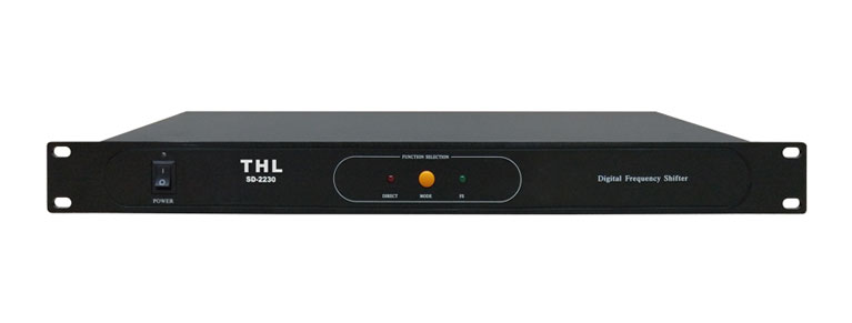
SD-2230
Technical Parameters
Model: SD-2230
Power supply: AC220V-230V, 50 / 60Hz
Microphone and line input frequency shift effect switch to select
Conference system local speakers to achieve independent effects of connection (EFX)
Frequency shift: 5Hz ± 1Hz
Acoustic gain gain: 5-14dB
Line input impedance: ≥5KΩ
Line output impedance: ≤600Ω
Frequency response: non-frequency shift state 20Hz-20KHz; frequency shift state 150Hz-15KHz
Instructions for use of function keys
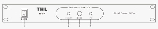
Front panel diagram
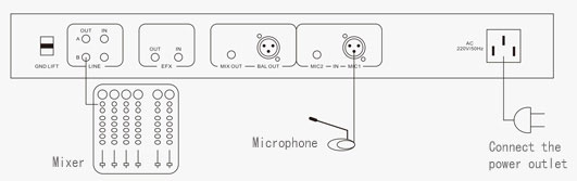
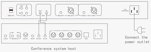
Rear panel diagram

1. The power switch. When the switch is pressed upward, the POWER indicator is on,
indicating that it is powered on. When the switch is pressed down, the indicator is off,
indicating that the power is off.
2. Non-frequency shift status indication. By (3) MODE control, light is on, that enter the
non-frequency shift state.
3. Frequency shift and non-frequency shift conversion button.
4. Frequency shift status indication. By (3) MODE control, the light is on, said to enter
the frequency shift state.
5. Ground switch, dial up equipment ground, down to dial the device disconnected from
the ground.
6. Line signal output. Dedicated to standard line signal connection.
7. Line signal input. Dedicated to standard line signal connection.
8. The effect of signal output. Effect (EFX) connector dedicated to conferencing
systems.
9. The effect of signal input. Effect (EFX) connector dedicated to conferencing systems.
10. The signal is not balanced output.
11. Signal balance output.
12. The microphone signal is not balanced input.
13. Microphone letter balance input.
14. An external AC power outlet.
Basic operation
1. Turn off the power switch (1) of the frequency shifter first, plug in the power (14),
connect the related equipment such as mixer, microphone or line, turn on the power.
Turn the frequency key on or off as needed.
2. The external line signal source connected to (7), adjust the mixer volume, depending
on the sound to the scene.
3. When you want to connect the local speaker of the conference system, please
connect to the matching EFX interface (refer to the connection diagram).
Connection diagram
1. Connect the microphone wiring diagram:
2.Connected with the conference system outside speaker connection diagram:
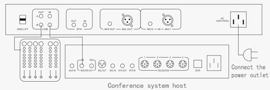
3. Meet the local speaker system connection diagram:
* The picture is for reference only, the appearance of the subject; subject to change without notice, the company has the final interpretation of the above content.